Servo motor is a DC motor that has an output feedback
indicates the position of rotation of the motor. Servo motors are widely used
as actuators requiring precise motor rotation position. If the ordinary DC
motor can only be controlled speed and direction of rotation, the servo motors
have an additional amount of parameters that can be controlled, which is a
position based on the angle / degrees.
In this tutorial I will cite an experiment with micro-type
servo motor SG90 (known as micro servo) that many available in the market. This is
called micro servo because of its small size and need small amout of current / voltage.
Specifications are approximately as follows:
SG90 Servo Motor Specs:
- Working voltage: 4.8 to 6 VDC
- Torque: 1.6 kg / cm
- Current: <500 mA
- Dimensions: 22 x 12.5 x 29.5 cm
- Weight: 9 g
- Rotation speed: 0.12 seconds / 60 degrees
Handle Servo Motor with Arduino Experiment
To handle the servo motor using the Arduino is easy
enough, you may even be able to do it for less than 5 minutes! The key is usage
of the library 'Servo.h' already provided by Arduino IDE. By declaring this library,
you can create an object that has a method 'write (degrees)' with 'degrees' parameter
is intended to show angle of rotation. For the above products, maximum angle is
1800, so you have a range of rotation angle between 00 - 1800 can be taken this
kind of servo motors. By using this servo motors we have not talked again about
the play direction (CW) or counter-clockwise (CCW) but the ‘angle’ of 00, 450, 900 and so on up to 1800. So, for example, if you issue the command ‘myservo.write
(90);’ after ‘myservo.write (0);’ then the servo motor will move
counter-clockwise. Then, if you issue the command ‘myservo.write (90);’ after ‘myservo.write
command (180);’, the servo motor will
automatically move clockwise.
The position 0 s.d 180 degree is determined by the
internal servo motor controller, and you simply give the command on the corner
where the motor will rotate through the command ‘myservo.write (degrees);’
To begin the experiment, prepare components as follows:
- Arduino board (Uno or others).
- Motor servo (e.g. a Tower Pro SG90 micro-servo)
- Jumper cables (3 pieces)
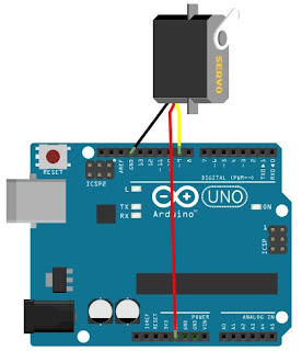
For servo motors, if you use the same type with mine then
you'll find three wires:
- The color red is a power cable, connected to the Arduino
5V pin
- The color black / brown is ground wires, connected to the
GND pin of Arduino board
- The color orange is the data cable / command, is connected
to pin 9 Arduino (the other pins may be substituted)
Servo Motor - Arduino Wiring
Then jumper cable between the servo motor and Arduino with the
configuration as above or can also be seen in the picture below
Servo Motor- Arduino Sketch
Once the prototype circuit is completed, it is time to fill the program handlers to Arduino sketch. Here they are:#include <Servo.h>
Servo myservo;
void setup()
{
myservo.attach(9);
}
void loop()
{
myservo.write(0);
delay(1000);
myservo.write(45);
delay(1000);
myservo.write(90);
delay(1000);
myservo.write(180);
delay(1000);
myservo.write(90);
delay(1000);
myservo.write(45);
delay(1000);
myservo.write(0);
delay(1000);
}
Copy this Arduino sketch to your
Arduino IDE, and upload the one to your Arduino board. If you don’t know how to
do this, please read in this article.
Once the sketch is uploaded to the Arduino and if your
wiring-connections are correct, then it should be the servo motor will now spin
into a position that was written in the sketch with a delay of about 1 second
(1000 ms). Note that the motor will back rotate in counter-clockwise to the start positions after reach maximal angle (1800) automatically. Congratz, you now able to handle a motor servo :). You can develop
another advanced experiment based on simple experiment above. And if you want to rotate the motor more than 1800 (e.g. 3600 or full rotation) I'll tell you the technique in How to Control Servo Motor Speed with Arduino tutorial :)


ConversionConversion EmoticonEmoticon